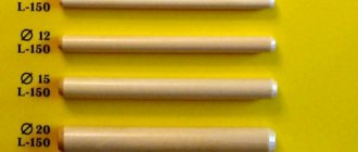
- Image of splines on a rod
- Threaded connections
- Riveted connections
Detachable and permanent connections:
Connections of parts in devices and machines are very diverse in their purpose, design, and manufacturing technology.
Connections are divided into detachable and permanent.
Detachable connections, their classification and purpose
Classification and purpose of detachable connections
Detachable connections include: threaded connections, connections using pins, wedges and keys, as well as toothed (spline) connections and others.
The detachable connection allows for repeated disassembly and subsequent reassembly; in this case, the integrity of the parts included in the connection is not compromised.
Threaded connections
Threaded connections are connections in which one of the parts has an external thread and the other has an internal thread. This connection is obtained by screwing one part onto another.
Bolted connection
It consists of a bolt, nut and washer and fastened parts. In parts 1 and 2, a hole is drilled with a diameter larger than the diameter of the bolt thread ( ). Insert bolt 3 into the hole, put on washer 5 and screw on nut 4 (Figure 17.1).
Features when performing a bolted connection:
- In the connection drawing, only three dimensions are indicated: thread diameter, bolt length and hole diameter in the parts being fastened;
- The bolt head and nut in the main image are usually shown with three faces;
Hairpin connection
A stud connection consists of a stud, nut, washer and fastened parts (Figure 17.2).
A socket is drilled into part 1 and a thread is cut into it. The threaded end of the pin 3 is screwed into the socket. A hole with a diameter of 1.1 d is drilled in part 2 and put on a pin. Then put washer 5 on the stud and screw on nut 4.
Features of making a hairpin connection:
- The dividing line of the fastened parts must coincide with the thread run-out of the screwed-in threaded end of the stud;
- The pin socket ends in a cone at an angle of 120°. This cone is of a technological nature and is obtained from a drill;
Screw connection
A screw connection consists of a screw and fastened parts (Figure 17.3).
In part 1, a socket is drilled into which a thread is cut. A hole with a diameter of 1.1 d is drilled in the attached part 2. The screw fits freely into the hole in part 2 and is screwed into part 1.
The conical head of the screw, called countersunk, should not protrude above the surface of the part.
The slot in the head for the screwdriver is positioned in the front and left views perpendicular to the front and profile planes of projection, and in the top view - conventionally at an angle of 45 degrees.
If the diameter of the screw head in the drawing is less than 12 mm, then the slot is shown as one thick line.
Constructive, simplified and conventional images of threaded connections
There are constructive, simplified and conventional images of fasteners and their connections.
When constructing a design, the dimensions of the parts are selected and drawn according to the relevant standards.
In a simplified representation, the dimensions of fasteners are determined by conditional relationships depending on the thread diameter.
A conventional image is used when the diameter of the rod is less than 2 mm.
In simplified illustrations, threads are shown along the entire length of the threaded fastener shank. Chamfers, roundings, and gaps between the part rod and the hole are not shown. In views obtained by projection onto a plane perpendicular to the thread axis, the thread on the rod is depicted by one circle corresponding to the internal diameter of the thread (the arc corresponding to the internal diameter of the thread is not depicted). These same views do not show the washers used in the connection. In simplified images, the end of the part hole is not shown (Figure 17.4).
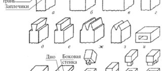
Wedge connection
A wedge connection is used when it is necessary to quickly disassemble and assemble machine parts to be connected, as well as tightening parts with adjusting the corresponding gaps between them (Figure 17.5).
A wedge is a block that has a bevel on one side with a certain slope. The wedge is rounded along the edges and ends.
Connection using pins
According to their shape, pins are divided into cylindrical and conical. Pins are used for mutual installation of parts, as well as connecting and safety parts.
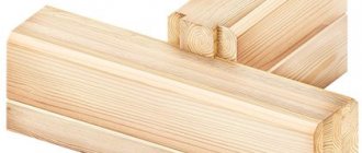
Keyed connection
Keys are used for detachable connection of parts when transmitting torque and axial force. A keyed connection consists of a wheel, a shaft and a key. A key is inserted into a special groove made on the shaft and the wheel is placed on the shaft so that the groove of the wheel hub hits the protruding part of the key.
The dimensions of the key design are standardized and depend on the diameter of the shaft. There should be a small gap between the upper non-working edge of the key and the edge of the hub groove. According to their design, keys are divided into prismatic (Figure 17.7, version 1), segmental (Figure 17.8) and wedge (Figure 17.9).
Designation examples:
- parallel key - Key GOST 23360-78, where 2 is the design (one end is rounded, the other is straight); 12×8 - section; 45 - key length;
- taper key - Key GOST 24068-80 (version 1 is not specified);
- segment key - Key GOST 24071-80, where 10 is the width; 16 - height of the key (version 1 is not specified).
Spline connections
A toothed, or splined, connection of a part with a shaft is formed by protrusions on the shaft and depressions of the same profile in the bushing or hub. (A spline connection can be considered a “multi-key” connection, in which the keys are integral with the shaft and located parallel to its axis). Compared to a keyed connection, it is capable of transmitting greater torques, and it is easy to carry out overall centering of the sleeve and shaft and their axial movement.
It is used in critical mechanical engineering structures.
There are standard splines with straight-sided and involute profiles in cross section. Triangular profile splines are not standardized. The slots in the longitudinal section are not conventionally hatched. A cross-section (section) is allowed to show the profile of one tooth and two cavities. The rest are indicated by circles: the tops of the teeth are a solid main line, and the valleys are a solid thin line. The image of a spline connection (Figure 17.11) with straight-sided splines differs from the image of a connection with involute splines (Figure 17.12) in that the latter has a dividing surface line (dash-dotted line).
The main convention in depicting spline joints is that the longitudinal section shows only that part of the bushing splines that is not covered by the shaft splines.
The symbol for straight-sided splines includes: the designation of the centering surface (letters D, d or b), the number of splines z, the diameter of the recesses d, the diameter of the projections D, the width of the spline b. In addition, the designations of the tolerance fields must be indicated.
Figure 17.13 shows an example of a designation in a connection, Figure 17.14 - on a shaft, Figure 17.15 - in a hole.
Centering surface D, z=8; d = 36mm, D = 40mm, b = 7mm.
Keyed
The keys secure the shaft with parts that transmit rotation and vibration. The design of such elements can be prismatic, wedge, segmental, tangential. Such fasteners form the following types of connections:
- Unstressed ones are carried out using prismatic segment keys. There is no pre-stress during assembly.
- Stressed ones are produced by tangential and segmental keys. Mounting stress appears during assembly. Used for complex mechanisms.
Permanent connections
Permanent connections include: riveted, welded, obtained by soldering, gluing, by pressing parts with tension.
Riveted connections
Riveted joints are used in connecting parts made of metals, which are generally difficult to weld, when connecting metal products with non-metal products (Figure 18.1). These connections are used in structures operating under the influence of shock and vibration loads.
A rivet is a round rod with a head at one end; the shape of the head varies.
Solder connection
When connecting by soldering, in contrast to welding, the soldering point is heated only to the melting temperature of the solder, which is much lower than the melting temperature of the material of the parts being connected. The connection of parts is achieved by filling the gap between them with molten solder. Soldering seams are conventionally depicted according to GOST 2.313-82 with a line twice as thick as the solid main line and are indicated by a symbol that is applied on a leader line from the solid main line.
A seam made along a closed line (along the perimeter) is indicated by a leader line ending in a circle with a diameter of 3...5 mm (Figure 18.2).
Bonding by gluing
The seam obtained during gluing is depicted in the same way as the seam during soldering, only a different icon is placed in the designation (Figure 18.3).
Welding
What makes them special? These types of joints are formed by heating and fusing the material at the attachment point to form a weld. This clutch is considered one of the most common.
There are several welding options. The most popular of them:
- Electric arc welding. Three main subtypes can be distinguished: automatic submerged welding (characterized by high productivity and quality, used in mass production), semi-automatic submerged arc welding (used for short intermittent welds), manual (lower productivity speed, quality depends directly on the experience of the welder).
- Contact welding. Used in mass production for thin sheet metal. The seam is made as an overlap.
One of the popular mounting options is shown in the photo.
Often used in suburban construction.
Designation of connecting thread type
It is often difficult to figure out in online catalogs which thread a particular part has - internal or external. This is especially true when there is no detailed drawing or photograph from the desired angle. In most cases, the abbreviations HP (external thread) and BP (internal thread) are used in part descriptions. For example, “1/2′ BP-HP-BP tee”.
Also, to designate the type of thread, the letters G (nut - internal thread, letter F in English) and Ш (fitting - external thread, letter M in English) can be used. For example, “Connection for towel rack is direct 1′-3/4′ G-W.”
The right-hand thread does not have any additional designations, but if there is a left-hand thread, then the letter L (L) is added to the abbreviation.
You might find it useful: “How to seal threaded water connections”
Rivet fixation
This coupling method is mainly used for joining sheet metal and shaped profiles. The technological hole in the surfaces is made by drilling, then a rivet is inserted.
Due to mechanical action, the rod and head are deformed, fill and fix the hole. This operation is performed manually and mechanized. Rivets are used to fix material that is not amenable to welding, soldering, gluing, and to parts where it is necessary to delay the destructive process.
What is a fitting
Fitting
- This is a part of the pipeline connection. This name is “foreign”; they like everything shortened so that it is easy to pronounce while running with your chewing mouth. Here is our definition of a fitting from GOST 15763-2005:
“ Pipeline connection parts
: Body parts (fittings, elbows, tees, crosses, plugs, plugs), connecting parts (sleeve and installation nuts, lock nuts, bolts, flanges) and sealing parts (cutting ring, clamping ring, welded and soldered nipples, gaskets, etc.), providing an assembled connection of pipelines.”
An uninformative name, isn't it? Actually, this article was written in order to consider these very details in more detail.
The term “coupling” has a more specific meaning, however, it also has a fairly wide list of parts. coupling
(plumbing) - this is a part of connecting two pipes to each other. The connected pipes can be either the same or different types (and diameters).
Couplings are usually threaded (cast iron, brass or bronze); combined, for joining metal with polypropylene (separable and non-separable); for soldering (polypropylene or copper); compression, for connecting metal with various plastics (cross-linked polyethylene or metal-plastic), which are more often called collets.
In practice, couplings for metal-plastic pipes and cross-linked polyethylene pipes (PEX-AL and PEX) are more often called fittings, although the term “coupling” is also applicable to them.