When designing any building, it is necessary to calculate the load-bearing capacity of beams. In individual construction, in the vast majority of cases, single-span wooden beams in the form of boards, beams or logs of various lengths are used. The proposed calculator will help you quickly select the optimal section and pitch of beams depending on the span length and expected loads.
To build a wooden house, it is necessary to calculate the load-bearing capacity of a wooden beam. Also of particular importance in construction terminology is the definition of deflection.
Without a high-quality mathematical analysis of all parameters, it is simply impossible to build a house from timber. That is why before starting construction it is extremely important to correctly calculate the deflection of wooden beams. These calculations will serve as a guarantee of your confidence in the quality and reliability of the building.
What is needed to make the correct calculation
Calculating the load-bearing capacity and deflection of wooden beams is not as simple a task as it might seem at first glance. To determine how many boards you need, as well as what size they should be, you need to spend a lot of time, or you can simply use our calculator.
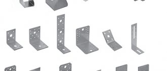
First, you need to measure the span that you are going to cover with wooden beams. Secondly, pay special attention to the fastening method. It is extremely important how deep the fixing elements will go into the wall. Only after this will you be able to calculate the load-bearing capacity along with the deflection and a number of other equally important parameters.
Length
Before calculating the load-bearing capacity and deflection, you need to know the length of each wooden board. This parameter is determined by the span length. However, this is not all. You must carry out the calculation with some margin.
When calculating, the material from which the house is made is of particular importance. If it is brick, the boards will be mounted inside the nests. Approximate depth is about 100-150 mm.
When it comes to wooden buildings, the parameters according to SNiPs vary greatly. Now a depth of 70-90 mm is sufficient. Naturally, this will also change the final load-bearing capacity.
If clamps or brackets are used during the installation process, then the length of the logs or boards corresponds to the opening. Simply put, calculate the distance from wall to wall and eventually you will be able to find out the load-bearing capacity of the entire structure.
Unfortunately, not everything depends on the imagination of the architect when it comes exclusively to mathematics. For edged boards, the maximum length is six meters . Otherwise, the load-bearing capacity decreases and the deflection becomes greater.
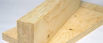
It goes without saying that it is now not uncommon for houses to have a span of 10-12 meters. In this case, glued laminated timber is used. It can be I-beam or rectangular . You can also use supports for greater reliability. Additional walls or columns are ideal for these purposes.
Flooring with boards 200 by 50 and other common sizes
These are the types of beams on a span of 4 meters that are allowed by the standards.
Most often, in the construction of wooden floors, boards and timber of the so-called running sizes are used: 50x150, 50x200, 100x150, etc. Such beams meet the standards ( after calculation ) if it is planned to cover an opening of no more than four meters.
For floors 6 or more meters long, the dimensions 50x150, 50x200, 100x150 are no longer suitable.
Wooden beam over 6 meters : subtleties
A beam for a span of 6 meters or more should not be made of timber and boards of standard sizes.
You should remember the rule: the strength and rigidity of the floor depend to a greater extent on the height of the beam and to a lesser extent on its width.
A distributed and concentrated load acts on the floor beam. Therefore, wooden beams for large spans are not designed “end-to-end”, but with a margin of strength and permissible deflection. This ensures normal and safe operation of the ceiling.
50x200 - overlap for an opening of 4 and 5 meters.
To calculate the load that the ceiling will withstand, you must have the appropriate knowledge. In order not to delve into the strength of strength formulas (and when building a garage this is definitely redundant), an ordinary developer just needs to use online calculators for calculating wooden single-span beams.
Leo060147FORUMHOUSE user
A self-builder is most often not a professional designer. All he wants to know is what beams need to be mounted in the ceiling so that it meets the basic requirements for strength and reliability. This is what online calculators allow you to calculate.
These calculators are easy to use. To make calculations of the required values, it is enough to enter the dimensions of the logs and the length of the span that they must cover.
Also, to simplify the task, you can use ready-made tables presented by the guru of our forum with the nickname Roracotta.
RoracottaFORUMHOUSE user
I spent several evenings to make tables that would be understandable even to a novice builder:
Table 1. It presents data that meets the minimum load requirements for the floors of the second floor - 147 kg/sq.m.
Note: since the tables are based on American standards, and the sizes of lumber overseas are somewhat different from the sections accepted in our country, you need to use the column highlighted in yellow in the calculations.
Table 2. Here is data on the average load for the floors of the first and second floors - 293 kg/sq.m.
Table 3. Here is the data for the calculated increased load of 365 kg/sq.m.
General information on calculation methodology
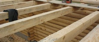
In most cases, single-span beams are used in low-rise construction. They can be in the form of logs, boards or beams. The length of the elements can vary over a wide range. In most cases, it directly depends on the parameters of the structure that you are going to build.
The role of load-bearing elements in the structure is performed by wooden blocks, the section height of which ranges from 140 to 250 mm, the thickness is in the range of 55–155 mm. These are the most commonly used parameters when calculating the load-bearing capacity of wooden beams.
Very often, professional builders use a cross beam installation scheme to strengthen the structure. It is this technique that gives the best results with minimal expenditure of time and materials.
If we consider the length of the optimal span when calculating the load-bearing capacity of wooden beams, then it is best to limit the architect’s imagination in the range from two and a half to four meters.
How to calculate load-bearing capacity and deflection
It is worth recognizing that over many years of practice in the construction craft, a certain canon has been developed, which is most often used to calculate the load-bearing capacity:
Calculating the deflection of a wooden beam is part of the formula presented above. The letter M indicates this indicator. To find out the parameter, use the following formula:
M=(ql 2 )/8
There are only two variables in the deflection calculation formula, but they are the ones that most determine what the load-bearing capacity of a wooden beam will ultimately be:
- The symbol q shows the load that the board can withstand.
- In turn, the letter l is the length of one wooden beam.
How important is it to correctly calculate the deflection?
This parameter is extremely important for the strength of the entire structure. The fact is that the durability of the timber alone is not enough for a long and reliable service, because over time its deflection under load can increase.
Deflection does not just spoil the aesthetic appearance of the ceiling. If this parameter exceeds 1/250 of the total length of the floor element , then the likelihood of an emergency will increase tenfold.
So why do you need a calculator?
The calculator presented below will allow you to instantly calculate deflection, load-bearing capacity and many other parameters without using formulas and calculations. Just a few seconds and the data on your future home will be ready.
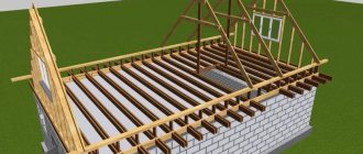
In private housing construction there are 3 types of structures that must be selected according to calculations. These are the foundation, floor and roof. Of course, you can do this without calculation, relying on your own experience or the experience of your friends and acquaintances. But then you risk your safety or your “wallet”. In other words, structures may not withstand the loads that fall on them, or they are built with greater reliability than required, and extra money is spent on this.
Below we will look at how you can calculate a wooden beam , i.e. select its optimal cross-section depending on operating conditions and material characteristics.
The calculation of beams should occur in the following sequence:
The calculation of wooden single-span floor support beams is carried out for strength , from the influence of design loads, and deformation (deflection) from the influence of standard loads. In order to simplify calculations, you can download a file in XLSX format, see below, for calculating wooden load-bearing single-span support beams (from boards and beams).
| Calculation form for wooden load-bearing single-span support beams (from boards and beams), in XLSX format |
To make the calculation, it is necessary to determine the pitch of the beams (the distance between the axes of the beams) and avoid the so-called “ fragility ” phenomenon of the floor. The pitch of beams in different sources ranges from 600 to 1040 mm (Linovich L.E. Calculation and design of parts of civil buildings, 1972; Osipov L.G., Serbinovich P.P., Krasensky V.E. Civil and industrial buildings, part 1, 1957), but the recommended step is no more than 750 mm .
I. Calculation of a wooden beam for strength
For example, there is an interfloor wooden ceiling of a residential building.
The distance between the load-bearing walls (beam span) is 5.0 m, the distance between the axes of the beams is 0.7 m. Drawing 1 Calculation:
1. Determine the area from which the loads on the floor beam will be collected. It is half the distance between the axes of the beams on one side and the other from the axis of the beam being calculated. In our case, the load collection area on the beam will be:
0.35 + 0.35 = 0.7 m (see Drawing 1)
2. Determine the load from the floor transferred to the beam. It consists of the self-weight of the floor and the temporary load on it.
Drawing 2
You need to find the weight of 1 m2 of each layer (see Drawing 2):
- floorboard, thick. - 0.05 m ; — sound insulation, thickness. - 0.1 m ; — lining board, thick. - 0.02 m .
The weight of 1 m3 of wood for the following species: pine, spruce, cedar, fir (take with a reserve for class of operating conditions 3 (wet) from Table G.1, set of rules “Wooden structures”) - 600 kg . The weight of 1 m3 of sound insulation (depending on the density of the insulation, take the example of URSA GEO M-15 with a density of 14 to 15 kg/m3) is 15 kg .
(600 x 0.05) + (15 x 0.1) + (600 x 0.02) = 43.5 kg/m2
3. Determine the weight of 1 linear meter of the beam. To do this, we take the estimated cross-section of the load-bearing beam, for example 0.12 x 0.2 (h) m , in which case the weight of 1 linear meter of the beam will be:
600 x 0.12 x 0.2 = 14.4 kg/m.p.
4. Find the standard and design loads from 1 m2 of floor without taking into account the floor beams .
Standard load
From the set of rules “Loads and Impacts”:
— the temporary standard load on the interfloor ceiling in residential buildings is 1.5 kPa or 150 kg/m2 ; — the standard load from the weight of the partitions is 0.75 kPa or 75 kg/m2 ; — standard values of loads on crossbars and floor slabs from the weight of temporary partitions should be taken depending on their design, location and nature of support on floors and walls. The specified loads can be taken into account as uniformly distributed additional loads, taking their standard values based on calculations for the proposed layout of partitions, but not less than 0.5 kPa or - 50 kg/m2 ). It is better to take into account the weight of the partitions to be installed - 75 kg/m2 .
The standard load from 1 m2 of flooring without taking into account floor beams will be:
43.5 + 150 + 75 = 268.5 kg/m2
Design load
From the set of rules “Loads and impacts”:
- load reliability coefficient for the weight of building structures for: concrete (with an average density of over 1600 kg/m), reinforced concrete, stone, reinforced stone, wood - 1.1 (used for flooring) ; — the temporary standard load on the interfloor ceiling in residential buildings is 1.5 kPa or 150 kg/m2 ; - standard values of loads on crossbars and floor slabs (in our case, a wooden floor) from the weight of temporary partitions should be taken depending on their design, location and nature of support on floors and walls. The specified loads may be taken into account as uniformly distributed additional loads, taking their standard values based on calculations for the proposed layout of partitions, but not less than 0.5 kPa. 1.3 - with a full standard value of less than 2.0 kPa; if the load on the floor is 2.0 kPa or more, then 1.2 - at the full standard value of the load; — standard values of loads on crossbars and floor slabs from the weight of temporary partitions should be taken depending on their design, location and nature of support on floors and walls. The specified loads can be taken into account as uniformly distributed additional loads, taking their standard values based on calculations for the proposed layout of partitions, but not less than 0.5 kPa or - 50 kg/m2 ). It is also better to take into account the weight of the partitions to be installed - 75 kg/m2 ; — standard values of loads on crossbars and floor slabs from the weight of temporary partitions should be taken depending on their design, location and nature of support on floors and walls. The specified loads may be taken into account as uniformly distributed additional loads, taking their standard values based on calculations for the proposed layout of partitions, but not less than 0.5 kPa. 1.3 - with a full standard value of less than 2.0 kPa; if the load on the floor is 2.0 kPa or more, then 1.2 - at the full standard value of the load.
The design load from 1 m2 of flooring without taking into account floor beams will be:
(43.5 x 1.1) + (150 x 1.3) + (75 x 1.3) = 340.35 kg/m2
5. Find the standard and design load from 1 m2 of flooring, taking into account the floor beams with a load collection width = 0.7 m.
Standard load
268.5 x 0.7 + 14.4 = 202.35 kg/l.m.
Design load
From the set of rules “Loads and impacts”:
- load reliability coefficient for the weight of building structures for: concrete (with an average density of over 1600 kg/m), reinforced concrete, stone, reinforced stone, wood - 1.1 (used for floor beams) ;
(340.35 x 0.7) + (14.4 x 1.1) = 254.09 kg/l.m.
6. Determine the bending moment of the beam:
Where,
M is the bending moment of the beam, in kgm; q is the design load per 1 linear meter. beams; l is the span of the beam.
(254.09 x 25) / 8 = 794.0 kgm
7. Determine the cross-section of the beam (strength calculation based on design loads)
From the set of rules “Wooden structures”:
— design bending resistance of wood — 130 kgf/m2
Find the moment of resistance of a wooden beam in cm3; for this we convert 794.0 kgm (bending moment of the beam) into kgcm .
794.0 x 100 = 79400 kgcm
Next, we find the moment of resistance itself - W
79400 / 130 = 610.8 cm3
Next, using tables 1 (Moments of resistance (W) and inertia (J) of boards and beams) or 2 (Moments of resistance (W) and inertia (J) of logs), based on the calculated moment of resistance of 610.8 cm3, select the section of the beam based on the accepted before starting to calculate the height of the beam - 20 cm .
From
Table 1, 10 x 20 with a moment of resistance of 667 is suitable for boards and beams , but it is better to take the next one with a margin of 12 x 20 , as expected. From Table 2, 20 cm with a moment of resistance of 785 is suitable for logs .
Table 1. Moments of resistance (W) and inertia (J) of boards and beams
Table 2. Moments of resistance (W) and inertia (J) of logs
It is impossible to use selected beams after strength calculations, because
they must also be checked for deflection.
II. Calculation of a wooden beam for deflection
The calculation of bending deformation is carried out based on standard loads.
1. Convert the previously obtained standard load to 1 linear meter. beams with a load collection width of 0.7 m - 202.35 kg/l.m in kgf/cm
202.35 / 100 = 2.024 kgf/cm
and beam span - 5 m in cm
5 x 100 = 500 cm
2. Calculate the deflection of the beam
Where
f is the deflection of the beam, in cm; q - standard load per 1 linear meter. beams; l is the span of the beam; E - modulus of elasticity of wood along the fibers - 100000; J is the moment of inertia of the beam from Table 1 (in our case we take the value 8000 for a selected beam 12 x 20 (h)) .
(5 / 384) x ((2.024 x 5004) / (100000 x 8000)) = 2.06 cm
3. Find the maximum deflection for our beam with a span of 500 cm
From the old set of rules “Wooden structures” ( not valid ), see table. 3:
— maximum deflection in fractions of the span for beams between floors — 1/250.
Table 3. Limit deflections in fractions of the span Now there are aesthetic and psychological requirements for the deflections of wooden beams in the set of rules “Loads and Impacts,” but they are less demanding, so it is better to use this table.
500 / 250 = 2 cm (maximum deflection for our beam)
4. Compare the resulting maximum deflection of the beam with the maximum calculated deflection.
Our deflection turned out to be more than 2 cm , namely 2.06 cm , which means we increase the cross-section of the beam to 15 x 20 .
We find the moment of inertia again, only in the formula we now substitute from the table the moment of inertia for a beam with a section of 15 x 20 (h) - 10000 . We also include in the formula the standard load, converted to kgf/cm , taking into account the weight of the beam 0.15 x 0.2 :
Beam weight - 600 x 0.15 x 0.2 = 18.0 kg/m.p.
Standard load - 268.5 x 0.7 + 18.0 = 205.95 kg/l.m.
Conversion of the standard load from kg/l.m to kgf/cm – 205.95 / 100 = 2.06 kgf/cm .
Substitute the obtained data into the formula
(5 / 384) x ((2.06 x 5004) / (100000 x 10000)) = 1.68 cm
This is less than the permissible deflection - 2.0 , which means we take a beam 5 m , with a cross-section of 15 x 20 .
Thus, after carrying out calculations of the wooden beam for strength and deflection under loads, we use wooden beams 5 m long, with a cross-section of 15 x 20 (h), with a step between the axes of the beams of 0.7 m, in the floor structure.
More complex calculations can be ordered from a licensed organization .
An example of calculating a wooden floor beam.
The calculation is performed in accordance with SNiP II-25-80 (SP 64.13330.2011) “Wooden structures” [1] and the use of tables [2].
Initial data.
It is required to calculate the beam between floors above the first floor in a private house.
Material: 2nd grade oak.
The service life of structures is from 50 to 100 years.
The composition of the beam is solid wood (not glued).
Beam spacing - 800 mm;
Span length - 5 m (5,000 mm);
Impregnation with fire retardants under pressure is not provided.
Design load on the floor - 400 kg/m2; on the beam - qр = 400·0.8 = 320 kg/m.
Standard floor load - 400/1.1 = 364 kg/m2; on the beam - qн = 364·0.8 = 292 kg/m.
Calculation.
1) Selection of design scheme.
Since the beam rests on two walls, i.e. it is hingedly supported and loaded with a uniformly distributed load, then the design diagram will look like this:
2) Strength calculation.
We determine the maximum bending moment for this design scheme:
Mmax = qp L 2 /8 = 320 5 2 /8 = 1000 kg m = 100000 kg cm,
where: qp - design load on the beam;
L is the span length.
We determine the required moment of resistance of a wooden beam:
where: R = Ri·mp·md·mв·mт·γсc = 130·1.3·0.8·1·1·0.9 = 121.68 kg/cm 2 - design resistance of wood, selected depending on calculated values for pine, spruce and larch at a humidity of 12% according to SNiP [1] - table 1 [2] and correction factors:
Rack made of boards or timber of the 1st grade
The table is compiled for scheme B
The amount of load that can be quite safely applied to a rack made of boards or timber of pine and spruce timber (Rb = 140 kg/cm2, the stand’s own weight is taken into account)
| Lumber GOST 24454-80 | Stand height, m | ||||||
| Width, cm | Thickness, cm | 1 | 2 | 3 | 4 | 5 | 6 |
| Safe permissible load on rack P, kg | |||||||
| Ultimate flexibility λmax ≤ 120 (columns) | |||||||
| 3,2 | 3,2 | 366* | |||||
| 4 | 3,2 | 458* | |||||
| 4 | 895* | ||||||
| 4,4 | 3,2 | 504* | |||||
| 4 | 985* | ||||||
| 4,4 | 1311* | ||||||
| 5 | 3,2 | 573* | |||||
| 4 | 1119* | ||||||
| 4,4 | 1490* | ||||||
| 5 | 2155* | ||||||
| 6 | 3,2 | 687* | |||||
| 4 | 1343* | ||||||
| 4,4 | 1788* | ||||||
| 5 | 2586* | ||||||
| 6 | 3694 | 1130* | |||||
| 7,5 | 3,2 | 859* | |||||
| 4 | 1678* | ||||||
| 4,4 | 2234* | ||||||
| 5 | 3232* | ||||||
| 6 | 4618 | 1413* | |||||
| 7,5 | 6528 | 2763* | |||||
| 10 | 3,2 | 1145* | |||||
| 4 | 2238* | ||||||
| 4,4 | 2979* | ||||||
| 5 | 4309* | ||||||
| 6 | 6157 | 1884* | |||||
| 7,5 | 8704 | 3684* | |||||
| 10 | 12651 | 8614 | 3874* | ||||
| 12,5 | 3,2 | 1432* | |||||
| 4 | 2797* | ||||||
| 4,4 | 3724* | ||||||
| 5 | 5387* | ||||||
| 6 | 7696 | 2355* | |||||
| 7,5 | 10880 | 4605* | |||||
| 10 | 15814 | 10767 | 4842* | ||||
| 12,5 | 20523 | 16483 | 9470 | 5309* | |||
| 15 | 3,2 | 1718* | |||||
| 4 | 3357* | ||||||
| 4,4 | 4469* | ||||||
| 5 | 6464* | ||||||
| 6 | 9235 | 2826* | |||||
| 7,5 | 13056 | 5526* | |||||
| 10 | 18976 | 12921 | 5810* | ||||
| 12,5 | 24628 | 19780 | 11365 | 6370* | |||
| 15 | 30145 | 26101 | 19370 | 11028 | 7030* | ||
| 17,5 | 3,2 | 2004* | |||||
| 4 | 3916* | ||||||
| 4,4 | 5214* | ||||||
| 5 | 7542* | ||||||
| 6 | 10775 | 3297* | |||||
| 7,5 | 15232 | 6447* | |||||
| 10 | 22139 | 15074 | 6779* | ||||
| 12,5 | 28732 | 23076 | 13259 | 7432* | |||
| 15 | 35169 | 30451 | 22598 | 12866 | 8202* | ||
| 17,5 | 41515 | 37468 | 30732 | 20454 | 13052 | 9025 | |
| 20 | 3,2 | 2290* | |||||
| 4 | 4476* | ||||||
| 4,4 | 5958* | ||||||
| 5 | 8619* | ||||||
| 6 | 12314 | 3768* | |||||
| 7,5 | 17408 | 7368* | |||||
| 10 | 25302 | 17228 | 7747* | ||||
| 12,5 | 32837 | 26373 | 15153 | 8494* | |||
| 15 | 40193 | 34801 | 25826 | 14704 | 9374* | ||
| 17,5 | 47446 | 42820 | 35122 | 23376 | 14917 | 10314 | |
| 20 | 54636 | 50583 | 43843 | 34414 | 22298 | 15433 | |
| 22,5 | 3,2 | 2577* | |||||
| 4 | 5035* | ||||||
| 4,4 | 6703* | ||||||
| 5 | 9696* | ||||||
| 6 | 13853 | 4239* | |||||
| 7,5 | 19584 | 8288* | |||||
| 10 | 28465 | 19381 | 8716* | ||||
| 12,5 | 36941 | 29670 | 17047 | 9556* | |||
| 15 | 45217 | 39152 | 29054 | 16542 | 10545* | ||
| 17,5 | 53377 | 48173 | 39513 | 26298 | 16782 | 11603 | |
| 20 | 61465 | 56906 | 49323 | 38716 | 25085 | 17362 | |
| 25 | 3,2 | 2863* | |||||
| 4 | 5595* | ||||||
| 4,4 | 7448* | ||||||
| 5 | 10774* | ||||||
| 6 | 15392 | 4710* | |||||
| 7,5 | 21760 | 9209* | |||||
| 10 | 31627 | 21535 | 9684* | ||||
| 12,5 | 41046 | 32966 | 18941 | 10617* | |||
| 15 | 50241 | 43502 | 32283 | 18381 | 11717* | ||
| 17,5 | 59308 | 53525 | 43903 | 29220 | 18646 | 12892 | |
| 20 | 68295 | 63229 | 54804 | 43018 | 27873 | 19291 | |
| 25 | 86124 | 82060 | 75308 | 65869 | 53741 | 37786 | |
| 27,5 | 3,2 | 3149* | |||||
| 4 | 6154* | ||||||
| 4,4 | 8193* | ||||||
| 5 | 11851* | ||||||
| 6 | 16932 | 5181* | |||||
| 7,5 | 23936 | 10130* | |||||
| 10 | 34790 | 23688 | 10652* | ||||
| Ultimate flexibility λmax ≤ 150 (uprights, attachments, support braces) | |||||||
| 3,2 | 3,2 | 366* | |||||
| 4 | 3,2 | 458* | |||||
| 4 | 895* | ||||||
| 4,4 | 3,2 | 504* | |||||
| 4 | 985* | ||||||
| 4,4 | 1311* | ||||||
| 5 | 3,2 | 573* | |||||
| 4 | 1119* | ||||||
| 4,4 | 1490* | ||||||
| 5 | 2155* | ||||||
| 6 | 3,2 | 687* | |||||
| 4 | 1343* | ||||||
| 4,4 | 1788* | ||||||
| 5 | 2586* | ||||||
| 6 | 3694 | 1130* | |||||
| 7,5 | 3,2 | 859* | |||||
| 4 | 1678* | ||||||
| 4,4 | 2234* | ||||||
| 5 | 3232* | ||||||
| 6 | 4618 | 1413* | |||||
| 7,5 | 6528 | 2763* | |||||
| 10 | 3,2 | 1145* | |||||
| 4 | 2238* | ||||||
| 4,4 | 2979* | ||||||
| 5 | 4309* | ||||||
| 6 | 6157 | 1884* | |||||
| 7,5 | 8704 | 3684* | |||||
| 10 | 12651 | 8614 | 3874* | ||||
| 12,5 | 3,2 | 1432* | |||||
| 4 | 2797* | ||||||
| 4,4 | 3724* | ||||||
| 5 | 5387* | ||||||
| 6 | 7696 | 2355* | |||||
| 7,5 | 10880 | 4605* | |||||
| 10 | 15814 | 10767 | 4842* | ||||
| 12,5 | 20523 | 16483 | 9470 | 5309* | |||
| 15 | 3,2 | 1718* | |||||
| 4 | 3357* | ||||||
| 4,4 | 4469* | ||||||
| 5 | 6464* | ||||||
| 6 | 9235 | 2826* | |||||
| 7,5 | 13056 | 5526* | |||||
| 10 | 18976 | 12921 | 5810* | ||||
| 12,5 | 24628 | 19780 | 11365 | 6370* | |||
| 15 | 30145 | 26101 | 19370 | 11028 | 7030* | ||
| 17,5 | 3,2 | 2004* | |||||
| 4 | 3916* | ||||||
| 4,4 | 5214* | ||||||
| 5 | 7542* | ||||||
| 6 | 10775 | 3297* | |||||
| 7,5 | 15232 | 6447* | |||||
| 10 | 22139 | 15074 | 6779* | ||||
| 12,5 | 28732 | 23076 | 13259 | 7432* | |||
| 15 | 35169 | 30451 | 22598 | 12866 | 8202* | ||
| 17,5 | 41515 | 37468 | 30732 | 20454 | 13052 | 9025 | |
| 20 | 3,2 | 2290* | |||||
| 4 | 4476* | ||||||
| 4,4 | 5958* | ||||||
| 5 | 8619* | ||||||
| 6 | 12314 | 3768* | |||||
| 7,5 | 17408 | 7368* | |||||
| 10 | 25302 | 17228 | 7747* | ||||
| 12,5 | 32837 | 26373 | 15153 | 8494* | |||
| 15 | 40193 | 34801 | 25826 | 14704 | 9374* | ||
| 17,5 | 47446 | 42820 | 35122 | 23376 | 14917 | 10314 | |
| 20 | 54636 | 50583 | 43843 | 34414 | 22298 | 15433 | |
| 22,5 | 3,2 | 2577* | |||||
| 4 | 5035* | ||||||
| 4,4 | 6703* | ||||||
| 5 | 9696* | ||||||
| 6 | 13853 | 4239* | |||||
| 7,5 | 19584 | 8288* | |||||
| 10 | 28465 | 19381 | 8716* | ||||
| 12,5 | 36941 | 29670 | 17047 | 9556* | |||
| 15 | 45217 | 39152 | 29054 | 16542 | 10545* | ||
| 17,5 | 53377 | 48173 | 39513 | 26298 | 16782 | 11603 | |
| 20 | 61465 | 56906 | 49323 | 38716 | 25085 | 17362 | |
| 25 | 3,2 | 2863* | |||||
| 4 | 5595* | ||||||
| 4,4 | 7448* | ||||||
| 5 | 10774* | ||||||
| 6 | 15392 | 4710* | |||||
| 7,5 | 21760 | 9209* | |||||
| 10 | 31627 | 21535 | 9684* | ||||
| 12,5 | 41046 | 32966 | 18941 | 10617* | |||
| 15 | 50241 | 43502 | 32283 | 18381 | 11717* | ||
| 17,5 | 59308 | 53525 | 43903 | 29220 | 18646 | 12892 | |
| 20 | 68295 | 63229 | 54804 | 43018 | 27873 | 19291 | |
| 25 | 86124 | 82060 | 75308 | 65869 | 53741 | 37786 | |
| 27,5 | 3,2 | 3149* | |||||
| 4 | 6154* | ||||||
| 4,4 | 8193* | ||||||
| 5 | 11851* | ||||||
| 6 | 16932 | 5181* | |||||
| 7,5 | 23936 | 10130* | |||||
| 10 | 34790 | 23688 | 10652* | ||||
| *— When you hover over a table cell with a number marked with an asterisk, a tooltip appears showing the maximum height of a rack of a given section and the maximum load at which the flexibility of the rack does not exceed the limit value for this type of structure. If the load or height of the rack exceeds the specified values, the rack will lose stability (bend more than the normalized limit). | |||||||
A post in Diagram B can support a load four times greater than a post in Diagram A. A post in Diagram B can support 8 times the load of Post A and twice that of rack B. The rack, fixed according to scheme D, can withstand a load 16 times greater than rack A, 4 times greater than rack B, and 2 times greater than rack B. (“Strengthening material for a carpenter”).
A post in Diagram B can support a load four times greater than a post in Diagram A. A post in Diagram B can support 8 times the load of Post A and twice that of rack B. The rack, fixed according to scheme D, can withstand a load 16 times greater than rack A, 4 times greater than rack B, and 2 times greater than rack B. (“Strengthening material for a carpenter”).
Recalculation of the table values for any other values of the calculated resistance R should be done by subtracting the beam’s own weight (volume, m³ × 0.51 kg/m³) from the values given in the table (white and beige cells) and multiplying the resulting number by the transition coefficient.
The transition coefficient is calculated by dividing the required and available design resistance. The data presented in the tables are made for calculated resistances R taken from SP 64.13330 edition of 2011. In 2022, a new edition of the building rules was released, in which the calculated resistances for pine, spruce and European larch wood, under equal loading conditions and operating conditions, are slightly changed. So, for example, R from a rectangular bar of the first grade in the 2011 rules was equal to 14 MPa (140 kg/cm²), and in the 2017 rules - 13.9 MPa (141 kg/cm²). Since the difference is insignificant, the tables are for now left within the framework of the 2011 rules.