I sell wooden products online in my city. About 7 years ago I bought a good set of hand-held circular saws. There were a bunch of stops in this set; I also purchased several over the years. Now I realize that they have fallen into disrepair, and the circular itself is not in the best condition. I decided to order a new one and make the stops myself. So to speak, to check, at the same time, what I have learned over all these years. Having finished, I decided that it would be useful for you to learn about how to make stops for a circular saw.
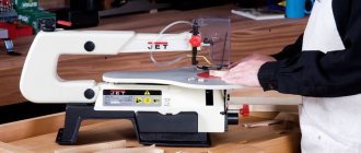
Source ytimg.com
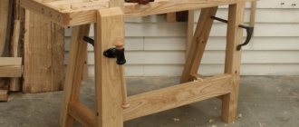
How to make a rip fence for a circular saw with your own hands?
- Peculiarities
- First execution
- Second design solution
The rip fence is an important tool when working with a circular saw. This device is used to make cuts parallel to the plane of the cutting saw blade and the edge of the material being processed. Usually, the manufacturer supplies one of the options for this device with a circular saw. However, the manufacturer’s option is not always convenient to use and in most cases does not satisfy the consumer’s needs. Therefore, in practice, you have to make one of the versions of this device with your own hands according to simple drawings.
There are several options for a constructive solution to this seemingly simple problem. All options have their advantages and disadvantages. You should choose a suitable design based on the needs that arise when processing various materials on a circular saw. Therefore, choosing the right solution must be taken seriously, responsibly and creatively.
This article discusses two of the simplest design solutions for creating an angular parallel stop for a circular saw with your own hands using existing drawings.
Peculiarities
What these design solutions have in common is a rack that moves relative to the cutting blade along the plane of the saw table. When creating this rail, it is proposed to use a standard extruded profile of a rectangular unequal flange angular section of aluminum or magnesium alloys. When assembling a parallel miter gauge with your own hands, other profiles of a similar cross-section can be used in accordance with the length and width of the working plane of the table, as well as the type of circular saw.
The proposed drawing options use a corner with the following dimensions (mm):
- wide – 70x6;
- narrow – 41x10.
Rip fence
A regular rip fence for a circular saw is a good example of how a small addition can make a big difference. Almost every hand-held circular saw is equipped with a rip fence for longitudinal cutting of a given width. This is a really useful device.
The standard stop has one drawback. For safety reasons, it is set to values that allow it to be used to make cuts less than 20–25 mm wide. This is done so that the stop does not interfere with the movement of the saw guard. But it is enough to attach a wooden block with self-tapping screws to the parallel strip of the standard stop - and its capabilities will increase, while the minimum cutting width will not be limited in any way.
Note! We must remember about safety - when making cuts of less than 15 mm, the block does not allow the protective casing to cover the saw blade.
Step-by-step instruction
So, the design details and the necessary tools have been selected, you can begin assembling and subsequent installation of the homemade carriage.
Step 1: Attaching the aluminum profiles
Since the carriage will “run along the saw table,” the first thing to do is guide grooves. To do this, take two U-shaped profiles, approximately equal to the length of the table. You can adjust the dimensions using a grinder.
At the same distance from the location of the cutting disc, circular saws draw two lines parallel to it. Then, using a hand router, U-profile holes are cut out along them, chips are blown out of them, and the corrugated pipes are secured in them using glue. After the glue dries, the grooves are ready.
Step 2: Making the carriage base
Next, the mobile base of the cross-cutting carriage is constructed. To do this, take two strips, which in thickness fit freely into the U-shaped groove. But there is one point here - the carriage will have to “slide” freely on the table, and for this it is raised above the table by 2-3 mm. To do this, nuts of equal thickness are placed into the profile grooves at equal distances, after which guide rails are laid on them.
Then glue is applied to them, which fixes the plywood base strip. To press it tighter, you can attach clamps on the sides.
When the resin has dried, the nuts are removed from the profile grooves and the master checks whether the carriage moves freely on them. After this, for ease of further use, the carriage is cut off on the sides along the table profile.
Step 3: Installation of walls
So, the base is ready and then the thrust walls are installed on it. To do this, take two wooden blocks: one of them is rigidly fixed, using self-tapping screws, along the edge closest to the master so that it is strictly perpendicular to the cutting edge of the saw blade; the second is secured along the top edge, but only on one side. This is necessary so that the master can align this wall strictly parallel to the bottom. The operation is performed using a square.
After the walls are leveled, a test cut is carried out. It has two purposes - it is used to saw holes in the walls and base of the carriage, and then by measuring the sawn workpiece, they check whether the right angle of the cut is correct.
Important . The height of the walls must be sufficient so that the cutting edge enters no more than half of it, otherwise the carriage may break during operation - and this is an unjustified risk when working with a circular saw.
Step 4: Making a Combination Square for Miter Cutting
So, a regular straight broach carriage is ready, but what if the cutter needs to cut something at a different angle, such as 60, 40 or 30 degrees? For such operations, you will need an additional structural element, which is called a “combined square”.
The name is put in quotation marks for a reason - the fact is that the base of the workpiece is really a square wooden platform. It is cut out so that it fits freely between the stops of the main carriage and one of the sides is fixed at the bottom wall.
Useful tricks and tips
There are such small devices that it is shameful to even consider them a tool. At the same time, they are great for cutting. These are the tricks of experienced masters.
Blank template
When cutting a large number of identical parts, you can use the first of them as a template for cutting subsequent copies. You just need to fasten a thrust piece on one side of the first sample with a width corresponding to the distance from the edge of the slab to the cutting disc. By installing such a template on the material to be cut, you can make many identical parts without markings.
Installation bars
The simplest part that makes it easier to install any stop and guide along the markings is a small cross-section block. There are cuts on it, the distance between which is equal to the segment from the end of the saw sole to the saw blade. Two such bars will help you install any guides quickly and accurately at the required distance from the marking line. All that remains is to secure the guide.
Pull-out protection
The protection can be any block whose width corresponds to the thickness of the workpiece being cut. If it is secured at the point where the saw blade exits the material being processed, it will act as a limiter and serve as protection against tearing out and chipping.
These devices are not limited to the range of useful homemade products that make working with a hand-held circular saw easier. These are the easiest to make. Others require time and skill. But craftsmen even make such a device as a protractor for a circular saw with their own hands. There would be a desire.
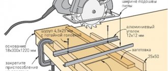
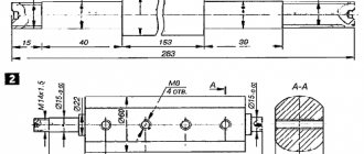
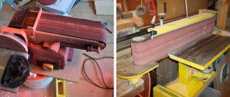
The circular fence and parallel stop are perhaps the main fixture on the circular table. That's why I decided to take this project seriously. I don’t spend extra time on sanding and shaping without the need for rounding on fixtures, I consider cutting, gluing, fastening with self-tapping screws and it’s done. In my opinion, extra beauty is not often appropriate, but strength is always needed. When working with difficult projects, I break them down into smaller components and work separately with it. Having at my disposal a narrow duralumin parallel stop (photo on the right), I had a number of inconveniences. The problem is that for each new cut you need to change the size of the stop installation; for this purpose, by moving the stop, we take into account the dimensions at the point where the cut begins to cut the workpiece and at the point where the cut exits relative to the saw blade, then we secure it with 2 handles. It's awkward and wastes time.
Step 1: Making the stop.
Cut three strips of laminated chipboard 1.1 m long and 8 cm wide, and then assemble them together to form a U-shaped profile. Using the internal dimensions of the profile, make 5 blank inserts for rigidity and insert them into the inside of the profile; they will create a square section required by the stop. The advantage of this stop is the ability to use it on both sides of the saw blade (photo on the left).
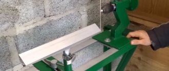
Step 2.7: Making a guide channel for the stop.
The channel guide for the stop is made of two slats, has the shape of a U-shaped profile and is bolted to the end of the circular table, perpendicular to the saw blade.
A simple carriage for a homemade circular saw
I will consider this option using the example of manufacturing a carriage for a desktop mini-circular machine J1F-DS100, which was previously converted. About this in this article
Considering that most craftsmen will make similar devices for other saws, in this case the manufacturing process itself and the design of the device (it is typical and common), and not the dimensions indicated in the attached drawing, are of interest.
Manufacturing sequence
So, in the manufactured machine we have a tabletop made of ordinary plywood.
(Don’t be confused by some difference in the size of the table top in further photos - I simply replaced the plywood with a slightly larger one, because I realized that the dimensions of this one were somewhat small)
Marking guides
In order to obtain a more or less usable tool in the future, it is necessary to accurately mark and mill the parallel grooves into which the carriage slides will be installed. The first necessary condition here is their parallelism to the plane of the saw blade . To do this, you need to “beat off this line” on the surface of the tabletop as accurately as possible. If there is no play or wobble in the disk fit, then it is enough to firmly attach a metal ruler to the disk and draw the desired line.
Milling grooves for runners
Now, parallel to this line, you need to mill two grooves on either side of the saw blade.
As a rule, craftsmen insert U-shaped metal profiles into these grooves to prevent wear of the grooves during operation and for better sliding of the skids.
To ensure a more or less stable position of the carriage, I approximately divided the tabletop into three equal parts and drew the required two lines. Parallelism is the most important condition here. You need to mill along the stop using any router. For this micro-machine I used an edge router.
Making runners
The runners can be made from hardwood, such as maple. I had oak on hand and sawed the slats from it. In general, if an aluminum U-shaped profile is inserted into the grooves, then the wear of the slides will be much less. I did without a profile due to the fact that I plan to buy a Proxon machine and the resource of this homemade product, provided that it is used infrequently, will be enough for me. Those who make homemade products “seriously and for a long time” keep this aspect in mind.
The slats should fit tightly in the grooves, but slide freely and not dangle in them. Otherwise, the carriage itself will dangle. The slats should be flush with the surface of the tabletop for ease of installation of the carriage platform on them.
Mounting the carriage base onto the skids
The next step is to install the carriage base on the skids. For this machine I take a 7 mm thick MDF sheet. Since I use PVA to install the base, I first stick masking tape on each edge of the slide to protect the surfaces from excess squeezed out glue.
Next, you can apply glue to the runners
and place the base blank on top of the runners, securing it with clamps at the gluing points
After the glue has dried, remove the carriage, remove the tape and check its sliding in the grooves
Marking the corners of the carriage
The carriage is installed in the grooves, the saw is turned on, and a cut is made in the front part of the base.
And relative to the line of this cut, the required 45 degrees are struck on both sides. This allows measurements to be taken from the actual position of the saw blade in the carriage cut.
Next, we cut down the corners and get the result as close as possible to the result.
Correction of carriage angles
We set the emphasis at any arbitrary distance from the disk and file 4 rough blanks
Putting them in a frame, we check the accuracy of the connection
At the slightest deviation from the correct angle, we trim the edge of the carriage on the desired side and again make a test fit, thus bringing it to the exact angle of 45 degrees.
After this, you can install the sides of the carriage flush with the cut of the base. From the rear side, we bring the edge of the carriage at a right angle to the saw blade, thereby ensuring the possibility of trimming parts at 90 degrees.
Additional accessories
- Blank template. If it is necessary to manufacture parts of the same type, you can use one of them as a guide template. To do this, a workpiece of the required length is cut and a thrust strip is attached to one end. The width of the rail must match the working distance. When working with this device, the thrust bar must fit snugly against the end of the workpiece. This way you can get a large number of parts of absolutely the same length without spending time marking the cutting line.
- Cutting square. For permanent use, you can make a cutting square. It consists of two massive wooden or plywood slats fastened with overlapping screws in the shape of the letter “T”. The length of the protruding ends of the “T” crossbar is adjusted to match the working distance of the circular saw. Positioning the aligned end of the crossbar against the marking line will allow for an accurate perpendicular cut.
- Edge stop. The standard configuration of the circular saw includes an angular (edge) stop. It allows you to make cuts parallel to the edge of the material being processed. Using a self-made edge stop, due to the expanded and longer base, you can get a cleaner and more accurate cut.
To make an edge stop, a stop strip and a base for a circular saw are cut out of 15 mm thick plywood. Keyways are selected in the base and thrust rack using a hand router. The dowels themselves are made from scraps of hard wood or from the same plywood and are attached to the grooves of the thrust strip. To strengthen the stop at an angle of 90°, another rail of sufficient width is attached to the stop rail, which will rest on the workpiece. Adjusting the distance of the cut from the edge of the workpiece is carried out by moving the stop bar along the guides and then fixing it using a locking screw.
To install the screw, a through groove is sawn through the base. To increase cutting accuracy and improve work safety, it is recommended to use two screws. A hole is made in the base plate for the saw blade and a mounting system for the circular saw is installed. The design of the fastening system can be very diverse and will depend on the specific brand of saw. The common point for all options should be reliable fixation of the circular saw and the ability to remove it from the device after finishing work. To make it easier to set the required cutting width of the material, a measuring tape is attached to the front surface of the base of the device.
Making a stop for a circular saw
There are 2 types of cutting stop: parallel and angular. Each option has its own characteristics that you need to know about before manufacturing.
Angular
The angle stop for the machine is used quite often. With its help, boards are cut accurately and quickly at right angles. It is also used for trimming boards from which the stop is made. You can easily make a device for sawing at an angle with your own hands.
- Take a sheet made of plywood for the base. Its thickness should not exceed 1 cm.
- Attach a guide bar to the base, the height of which is no more than 2 cm.
- It is recommended to fix the stop at the bottom, which is perpendicular to the guide. It must be made from the same piece of material.
- Separate unused parts of the bar. The distance from the guide to the saw blade is calculated individually each time, so it is recommended to attach it to the material being processed from the corner with clamps.
- Use fastening devices made of wooden washers.
- Press the wing nut onto the screw.
Using a rail miter box
The use of a rail miter box is advisable if you need to quickly and efficiently process a large number of boards. Used in production:
- two identical metal corners;
- Chipboard or plywood sheet at least 1.5 cm thick for the base;
- four pairs of bolts.
Metal corners are installed on a plywood base.
The corners are fastened with bolts - which act as studs - at the corners of the base. The corners are placed on the same plane strictly parallel to each other. This is necessary so that the circular saw slides freely along the rail during operation and does not jam or slide off it. Using pins, the fixing height of the corners is set, which is necessary for the free movement of the processed material between the base and the rails. In this case, the edge of the cutting circle should not be too high from the base, while at the same time eliminating the possibility of damage to it. To make the saw glide easier, fluoroplastic strips are glued to the corners or a frame with wheels is made for it, which is preferable.
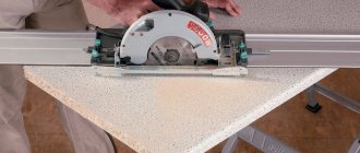
The source material is cut into workpieces using a rip fence for a circular saw during operation. You can easily make it with your own hands from a wooden plank or a metal corner, securing it to a workbench with clamps.
Having made the markings on the workbench, the tire is set at the required distance from the stop and, resting the end of the board against it, the workpiece is cut off.
If it is necessary to cut the workpiece at an angle, it is fixed using a stop made of a pair of screws screwed into the base, and the angular inclination of the cut is set using a protractor.
Making a laminate tire
This method of making a carriage for a circular saw with your own hands is the easiest to implement; it uses readily available raw materials.
Required:
- laminate sheet;
- several screws;
- A4 piece of paper.
Three blanks are made from the laminate. One of them will serve as the basis for the guide. The other two are cut in the shape of two strips, each about half a meter long. For both, the edges are aligned on one side using a milling cutter. Using self-tapping screws, the strips are attached to each other parallel to the straight edges. The width of the groove between them is checked using an A4 piece of paper, inserting it into the device and scrolling.
The tire is secured to the base of the circular saw using side support fasteners. If the warranty period of the saw has already expired, for greater reliability of fastening you can use the body of the circular saw by making an additional hole in it.
Before starting work, the homemade guide must be extended in front of the circular saw handle. In this case, it is necessary that the guide is covered by the nose of the sole by several centimeters. For perfect compatibility of the edges of the guide strips with the marks on the material, you need to carefully saw off the uneven strips with a laminate cutting disc.
DIY table for router and circular saw
Where to start making a table? Like any other design, it must start with a working sketch. It is this document that will give a clear idea of what exactly the table will be like and what is needed to make it. The drawing is developed indicating the actual dimensions, which in the process will make it possible to calculate the required amount of materials.
Basic requirements for the working surface of joinery machines
The first thing that a milling machine and a circular saw have in common is the need for a working surface or, in other words, a table top. She must be:
- flat and smooth. Otherwise, deformation of the workpieces is possible;
- tough. Deflection of the working surface during use is not allowed. This may lead to a change in the specified processing parameters, which will lead to defective parts;
- made of material that allows you to easily install stops, clamping strips, combs, shields and guard casings to maintain safety during work;
- made in accordance with the dimensions of the workpieces intended for processing. All operations must be carried out without constraint or restrictions.
Basic requirements for table design
A standard table for a circular saw has dimensions of 1.2x1.2 meters.
In certain cases, the size can be changed by the user to accommodate non-standard workpieces. The height of the working surface is 0.85 meters. It may be more or less, depending on the growth of the service personnel. As a basis for a universal table, you can use the tabletop of a machine for a circular saw. Since the saw blade is located on the left side of the table, the router can be placed on the right. It is installed taking into account the space for the workpieces being processed. It should be remembered that the master performing the milling should be at the end on the right side of the table, and not in front of the router. This requires the installation of maximum guarding of all moving parts to prevent human contact.
Last checks
The previous operations performed will improve the quality of work on the circular saw, but it is also worth taking care of safety. Take a look at the riving knife, which should be in the middle of the disk and at right angles to the plane of the table. This is checked with a flat bar and the same drawing square.
The principle of adjusting the riving knife is similar for most sawing machines: loosen the nuts or screws, change the inclination of the stand and the outlet of the angle, then tighten the fasteners.
All that remains is to check the side wing extensions and, if necessary, align the parts at table level. Try to carry out such maintenance at least once a year and your “circular” will always be in good working order. And for cheap machines, such a check is recommended immediately after purchasing the equipment.